Showing posts with label Systems and Networks. Show all posts

Monday, May 24, 2021

TCP handshake / TCP 3-way handshake

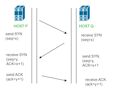
  •  The TCP handshake. TCP uses a three-way handshake to establish a reliable connection. The connection is full duplex, and both sides synchronize (SYN) and acknowledge (ACK) each other. The exchange of these four flags is performed in three steps—SYN, SYN-ACK, and ACK

https://www.sciencedirect.com/topics/computer-science/three-way-handshake


  • The client chooses an initial sequence number, set in the first SYN packet. The server also chooses its own initial sequence number, set in the SYN/ACK packet shown in Figure 3.8. Each side acknowledges each other's sequence number by incrementing it; this is the acknowledgement number. The use of sequence and acknowledgment numbers allows both sides to detect missing or out-of-order segments.

Once a connection is established, ACKs typically follow for each segment. The connection will eventually end with a RST (reset or tear down the connection) or FIN (gracefully end the connection).
https://www.sciencedirect.com/topics/computer-science/three-way-handshake

By default, Wireshark converts all sequence and acknowledgement numbers into relative numbers. This means that all SEQ and ACK numbers always start at 0 for the first packet seen in each conversation


TCP SYN
Since this is the start of the TCP connection, the client sends a TCP packet with the sequence number set to 0. 
the first TCP packet sent from the client to the server includes SYN seq=0 in the Info field.  
see that “Sequence number: 0” and expand the “Flags” field in the details section to also see that the Syn bit is “Set”.


https://madpackets.com/2018/04/10/tcp_handshake/

TCP SYN-ACK
see the server respond with a SYN-ACK message with Seq=0 and Ack=1.
for the TCP handshake example, if the client sends  a seq=0, the server responds with ack=1. The packet is identified as a SYN-ACK packet by looking at the packet listing field and also by looking at the packet details field

TCP ACK
the TCP session sends an acklowledgement to complete the 3-way handshake. (Reminder that the Syn bit is not set). Note that the syn=1 and ack=1, because the TCP-Syn from the server sent a seq=0 and ack=1 in the TCP Syn-Ack 

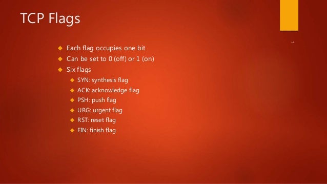
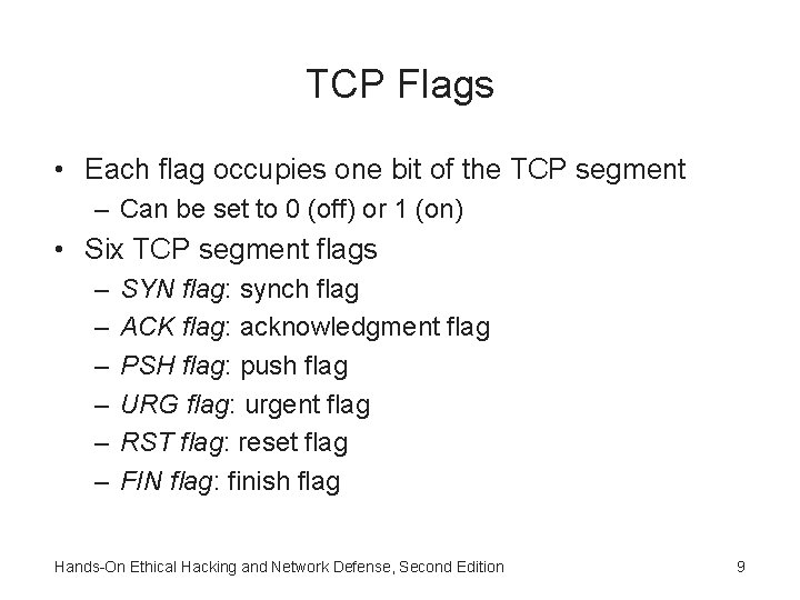
  • The TCP level of the TCP/IP transport protocol is connection-oriented. Connection-oriented means that, before any data can be transmitted, a reliable connection must be obtained and acknowledged. TCP level data transmissions, connection establishment, and connection termination maintain specific control parameters that govern the entire process. The control bits are listed as follows:

URG: Urgent Pointer field significant
ACK: Acknowledgment field significant
PSH: Push Function
RST: Reset the connection
SYN: Synchronize sequence numbers
FIN: No more data from sender

There are two scenarios where a three-way handshake will take place:

Establishing a connection (an active open)

Ending a connection (an active close)

Frame 1:
It's a request to the server to synchronize the sequence numbers. It specifies its initial sequence number (ISN). The ISN is incremented by 1 (8221821+1=8221822), and is sent to the server. To start a connection, the client and server must synchronize each other's sequence numbers.
The Acknowledgment field (ack: 0) is set to zero because it's the first part of the three-way handshake.

Frame 2:
the server, BDC3, sends an ACK and SYN segment (TCP .A..S.)
In this segment, the server is acknowledging the request of the client for synchronization.
Meanwhile, the server is also sending its request to the client for synchronization of its sequence numbers. 
The server transmits an acknowledgment number (8221823) to the client. 
The acknowledgment is just proof to the client that the ACK is specific to the SYN the client initiated. 
The process of acknowledging the client's request allows the server to increment the client's sequence number by one and uses it as its acknowledgment number

Frame 3:
the client sends an ACK segment (TCP .A....)
 In this segment, the client is acknowledging the request from the server for synchronization. The client uses the same algorithm the server implemented in providing an acknowledgment number. The client's acknowledgment of the server's request for synchronization completes the process of establishing a reliable connection and the three-way handshake.

Ending a connection
Although the three-way handshake only requires three packets to be transmitted over our networked media, the termination of this reliable connection needs to transmit four packets. Because a TCP connection is full-duplex (data can flow in each direction independent of the other), each direction must be terminated independently.

Frame 4:
the client sending a FIN that's accompanied by an ACK (TCP .A...F). This segment has two basic functions. First, when the FIN parameter is set, it will inform the server that it has no more data to send. Second, the ACK is essential in identifying the specific connection they've established

Frame 5:
the server acknowledging the FIN that was transmitted from the client.

Frame 6:
After receiving the FIN from the client computer, the server will ACK. Even though TCP has established connections between the two computers, the connections are still independent of one another. So the server must also transmit a FIN (TCP .A...F) to the client.

Frame 7:

The client responds in the same format as the server, by ACKing the server's FIN and incrementing the sequence number by 1.
https://docs.microsoft.com/en-us/troubleshoot/windows-server/networking/three-way-handshake-via-tcpip

  • SYN: The active open is performed by the client sending a SYN to the server. The client sets the segment's sequence number to a random value A.
SYN-ACK: In response, the server replies with a SYN-ACK. The acknowledgment number is set to one more than the received sequence number i.e. A+1, and the sequence number that the server chooses for the packet is another random number, B.
ACK: Finally, the client sends an ACK back to the server. The sequence number is set to the received acknowledgement value i.e. A+1, and the acknowledgement number is set to one more than the received sequence number i.e. B+1.
At this point, both the client and server have received an acknowledgment of the connection. The steps 1, 2 establish the connection parameter (sequence number) for one direction and it is acknowledged. The steps 2, 3 establish the connection parameter (sequence number) for the other direction and it is acknowledged. With these, a full-duplex communication is established.
https://ddos-guard.net/en/terminology/protocols/tcp-3-way-handshake
3 Way Handshaking by Wireshark




What Is a Three-Way Handshake in TCP?


Wednesday, March 31, 2021

SSL Forward Proxy

Implementing SSL Forward Proxy on a Single BIG-IP System

Overview: SSL forward proxy client and server authentication

With the BIG-IP system's SSL forward proxy functionality, you can encrypt all traffic between a client and the BIG-IP system, by using one certificate, and to encrypt all traffic between the BIG-IP system and the server, by using a different certificate.

A client establishes a three-way handshake and SSL connection with the wildcard IP address of the BIG-IP system virtual server. The BIG-IP system then establishes a three-way handshake and SSL connection with the server, and receives and validates a server certificate (while maintaining the separate connection with the client). The BIG-IP system uses the server certificate to create a second unique server certificate to send to the client. The client receives the second server certificate from the BIG-IP system, but recognizes the certificate as originating directly from the server.

https://techdocs.f5.com/kb/en-us/products/big-ip_ltm/manuals/product/bigip-ssl-administration-11-6-0/13.html

SSL Forward Proxy Overview

Secure Sockets Layer (SSL) is an application-level protocol that provides encryption technology for the Internet. SSL, also called Transport Layer Security (TLS), ensures the secure transmission of data between a client and a server through a combination of privacy, authentication, confidentiality, and data integrity. SSL relies on certificates and private-public key exchange pairs for this level of security.

Server authentication guards against fraudulent transmissions by enabling a Web browser to validate the identity of a Web server. Confidentiality mechanisms ensure that communications are private. SSL enforces confidentiality by encrypting data to prevent unauthorized users from eavesdropping on electronic communications. Finally, message integrity ensures that the contents of a communication have not been tampered with.

SSL forward proxy is a transparent proxy; that is, it performs SSL encryption and decryption between the client and the server, but neither the server nor the client can detect its presence. SSL forward proxy ensures that it has the keys to encrypt and decrypt the payload:

  • For the server, SSL forward proxy acts as a client—Because SSL forward proxy generates the shared pre-master key, it determines the keys to encrypt and decrypt.

  • For the client, SSL forward proxy acts as a server—SSL forward proxy first authenticates the original server and replaces the public key in the original server certificate with a key that is known to it. It then generates a new certificate by replacing the original issuer of the certificate with its own identity and signs this new certificate with its own public key (provided as a part of the proxy profile configuration). When the client accepts such a certificate, it sends a shared pre-master key encrypted with the public key on the certificate. Because SSL forward proxy replaced the original key with its own key, it is able to receive the shared pre-master key. Decryption and encryption take place in each direction (client and server), and the keys are different for both encryption and decryption.

https://www.juniper.net/documentation/en_US/junos-space18.1/topics/concept/junos-space-ssl-forward-proxy-overview.html

SSL Forward Proxy

When you configure the firewall to decrypt SSL traffic going to external sites, it functions as an SSL forward proxy. Use an SSL Forward Proxy decryption policy to decrypt and inspect SSL/TLS traffic from internal users to the web. SSL Forward Proxy decryption prevents malware concealed as SSL encrypted traffic from being introduced into your corporate network by decrypting the traffic so that the firewall can apply decryption profiles and security policies and profiles to the traffic.
In SSL Forward Proxy decryption, the firewall is a man-in-the-middle between the internal client and the external server. The firewall uses certificates to transparently represent the client to the server and to transparently represent the server to the client, so that the client believes it is communicating directly with the server (even though the client session is with the firewall), and server believes it is communicating directly with the client (even though the server session is also with the firewall). The firewall uses certificates to establish itself as a trusted third party (man-in-the-middle) for the client-server session (for details on certificates, see Keys and Certificates for Decryption Policies).

https://docs.paloaltonetworks.com/pan-os/8-1/pan-os-admin/decryption/decryption-concepts/ssl-forward-proxy


Difference Between SSL Forward-Proxy and Inbound Inspection Decryption Mode

When configuring SSL decryption policy in order to define SSL traffic eligible for decryption, you have to make a choice between 2 different types/modes:

  • SSL Forward-Proxy
  • SSL Inbound Inspection
In Forward-Proxy mode, PAN-OS will intercept the SSL traffic which is matching the policy and will be acting as a proxy (MITM) generating a new certificate for the accessed URL. This new certificate will be presented during SSL Handshake to the Client accessing website with SSL. This certificate will be signed with the self-signed CA certificate or another certificate specified

In Inbound Inspection mode, PAN-OS will not act as a proxy with SSL traffic matching the policy. PAN-OS will try to decrypt this SSL traffic 'on-the-fly' by eavesdropping the SSL handshake and using associated Certificate (Key Pair) configured in decryption policy
This decryption mode can only work if you have control on the targeted Web Server certificate to be allow to import Key Pair on Palo Alto Networks Device
https://knowledgebase.paloaltonetworks.com/KCSArticleDetail?id=kA10g000000ClV8CAK


Wednesday, December 30, 2020

Sistem odası

  •  Bir Sistem odasınde bağıl nem ile ilgili olarak iki olası tehlike bulunur:

1. Elektrostatik deşarj: Elektrostatik deşarj olasılığı, nem çok düşük olduğunda gerçekleşir. Ayrıca, bu olasılık sıcaklık düşük olduğunda da artar. Elektrostatik deşarj insanlar tarafından oldukça zor fark edilebilir ve genelde yaralanmalara yol açmaz. Ancak, 10 Volt değerindeki bir deşarj donanıma hasar verebilir.

2. Korozyon: Bu durum metalik bir donanım, donanım ıslandığında veya havadaki su yoğuşmasının sonucu olarak küçük damlalar oluştuğunda veya suya maruz kaldığında oluşur.

Örneğin: Yüksek nem bulunan bir ortamda, sunucuların içerisindeki elemanlar hasar görebilir ve veri kaybı yaşanabilir. Buradaki ana nokta, yoğuşma ve elektrostatik deşarjın engellendiği bir ortamda, nemin optimum bir aralıkta tutulacak şekilde dengelenmesidir. Bunun için, en uygun bağıl nem aralığı %40 ile %55 arasıdır. 

(Bu değer aynı zamanda TIA/EIA 942 standardıyla önerilir)

https://hassasklima.com/bilgi-bankasi/tag/sistem%20odas%C4%B1%20nem%20oran%C4%B1%20ne%20olmal%C4%B1.html


  •  Havadaki nem oranının aşırı yükselmesi veya düşmesi bilgisayar sistemlerine zarar verebilir. Nemin çok az olması, statik elektrik yüklenme ve aktarımlarını arttırarak manyetik teyp ve benzeri bileşenlerde sorunlara yol açabilir.  Nem oranının çok yükselmesi ise, bilgisayar sistemlerinizin devrelerinde kısa devrelere  kadar uzanan sorunlara neden olabilir.  Söz konusu olumsuzlukların önlenebilmesi için yüksek güvenilirlik gerektiren ortamlarda nem düzeyi belirli sınırlar arasında tutulmalı ve  nem düzeyinin belirlenen sınırlar dışına çıkması durumunda alarm sistemleri devreye girmelidir.

 https://sistemnetwork.karabuk.edu.tr/sistem_odasi/sistem_odasi.html

Sunday, June 9, 2019

WAN optimization (WAN acceleration)


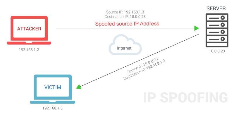
  • WAN Optimization Protocol Spoofing

Protocol Spoofing is an essential part of data communications that helps to enhance performance
Protocol spoofing evolved in the 1980s and is used as a data compression technique to improve throughput levels and thereby increase performance.
While used as a data compression technique, the protocol headers and trailers are either removed completely or cut down, and finally reconstructed at the end points
The technique of protocol spoofing involves communication devices (modem, router), host machines, compatible remote devices and communication links

Spoofing, in computer security, pertains to different forms of data falsification or misrepresentation. The forgery of headers to send out misleading information is a form of spoofing. While protocol spoofing generally refers to the method of enhancing performance, there are many other types of protocol spoofing that perform different functions – both advantageous and disadvantageous

Transmission Control Protocol (TCP) Spoofing
TCP spoofing enables to reduce transmission delays and performance limitation due to higher bandwidth. The algorithm used by TCP greatly causes delays in connections during startup. TCP spoofing involves a spoofing router, which terminates the local TCP connection and interprets the TCP to protocols that have the capacity to reduce long delays across satellite links.

File Transfer Spoofing
File Transfer Protocols and Error Correction Protocols operate through computing and assigning a checksum for a data packet

RIP/SAP Spoofing
RIP and SAP are used for broadcasting network information in a periodic way.

The other types of spoofing techniques that are involved in misrepresentation of information are Address Resolution Protocol (ADP) Spoofing, Internet Protocol (IP) Address Spoofing, etc. Those protocol spoofing techniques that adversely affect the users can be controlled by using counter methods such as packet filtering, egress filtering, data authorization and other techniques.
https://www.wanoptimization.org/protocol_spoofing.php


  • WAN optimization (WAN acceleration)

WAN optimization, also known as WAN acceleration, is the category of technologies and techniques used to maximize the efficiency of data flow across a wide area network (WAN).

WAN optimization encompasses:

    traffic shaping, in which traffic is prioritized and bandwidth is allotted accordingly.
    data deduplication, which reduces the data that must be sent across a WAN for remote backups, replication, and disaster recovery.
    compression, which shrinks the size of data to limit bandwidth use.
    data caching, in which frequently used data is hosted locally or on a local server for faster access.
    monitoring the network to detect non-essential traffic.
    creating and enforcing rules about downloads and Internet use.
    protocol spoofing, which is a method of bundling chatty protocols so they are, in effect, a single protocol.

https://searchnetworking.techtarget.com/definition/WAN-optimization-WAN-acceleration

  • How WAN Optimization Works 

WAN performance issues
    Latency: This is the back-and-forth time resulting from chatty applications and protocols, made worse by distance over the WAN. One server sends packets, asks if the other server received it, the other server answers, and back and forth they go. This type of repeated communications can happen 2,000 to 3,000 times just to send a single 60MB Microsoft PowerPoint file. A somewhat simple transaction can introduce latency from 20 ms to 1,200 ms per single file transaction.
    TCP window size: Adding more bandwidth won’t necessarily improve WAN performance. Your TCP window size limits throughput for each packet transmission. While more bandwidth may give you a bigger overall pipe to handle more transactions, each specific transaction can only go through a smaller pipe, and that often slows application performance over the WAN.

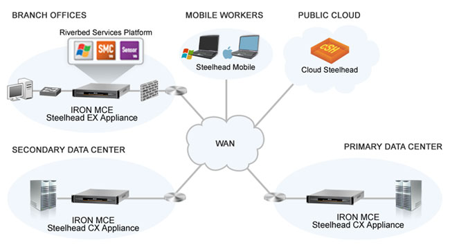
SteelHead is a bookend technology in which one Steelhead sits at the data center and another at the edge. SteelHead works with any WAN because it sits behind routers, which terminate the WAN at each end.
The bookended SteelHead analyzes each packet as it goes on and off the routers.

SteelHead, utilizes a combination of three technologies to boost WAN performance.
#1. Data streamlining
 Don’t resend redundant data: A process known as data de-duplication removes bytes from the WAN. Data that is accessed repeatedly by users over the WAN is not repeatedly resent
 Scalable data referencing looks at data packets: Let’s say a user downloads a document from a file server. At the sending and receiving locations, SteelHead sees the file and breaks the document into packets and stores them. Then the user modifies the document and emails it back to 10 colleagues at the file’s original location. In this case the only data sent over the WAN are the small changes made to the document and the 16-byte references that tells the SteelHead device at the other end how to reassemble the document.
 SteelHead cares about data: Data is data to SteelHead, no matter what format or application it comes from. That means far less of it needs to be sent across the WAN. As an example, imagine how many times the words “the” and “a” appear in files from various applications. SteelHead doesn’t care; these bytes look the same and therefore need not be sent. This type of de-duplication can remove 65–95% of bytes from being transmitted over the WAN.

#2. Transport streamlining
The fastest round trip is the one you never make: Transport streamlining makes TCP more efficient, which means fewer round trips and data per trip. For example, traditional TCP does what’s known as a “slow start process,” where it sends information in small chunks and keeps sending increasingly larger chunks until the receiving server can’t handle the chunk size. Then it starts again back at square one and repeats the process. Transport streamlining avoids the restart and just looks for the optimal packet size and sends packets only in that size

#3. Application streamlining
Lastly, application streamlining is specially tuned for a growing list of application protocols including CIFS, HTTP, HTTPS, MAPI, NFS, and SQL.
https://www.riverbed.com/newsletter/how-wan-optimization-works.html


Tuesday, October 16, 2018

backbone networks

backbone network connects multiple LANs
In backbone network station/endpoint/server/pc is not directly connected to backbone

categories:
bus backbone
star backbone
connecting remote LANs

backbone handles a total load higher than one of the LANs backbone connecting
A backbone is a part of computer network that interconnects various pieces of network, providing a path for the exchange of information between different LANs or subnetworks. A backbone can tie together diverse networks in the same building, in different buildings in a campus environment, or over wide areas. Normally, the backbone's capacity is greater than the networks connected to it.
A large corporation that has many locations may have a backbone network that ties all of the locations together, for example, if a server cluster needs to be accessed by different departments of a company that are located at different geographical locations. The pieces of the network connections (for example: ethernet, wireless) that bring these departments together is often mentioned as network backbone. Network congestion is often taken into consideration while designing backbones.

A distributed backbone is a backbone network that consists of a number of connectivity devices connected to a series of central connectivity devices, such as hubs, switches, or routers, in a hierarchy. 

A collapsed backbone (inverted backbone, backbone-in-a-box) is a type of backbone network architecture
In the case of a collapsed or inverted backbone, each hub provides a link back to a central location to be connected to a backbone-in-a-box. That box can be a switch or a router. The topology and architecture of a collapsed backbone is a star or a rooted tree.

concepts & protocols
OSPF
BGP,MBGP
IS-IS
QoS
VRRP
MPLS:LDP,RSVP
L3 VPN
VRF /context routing
Policy based routing
Aggregation

Switching
VLAN
Trunk
802.1q VLAN tagging
STP/RSTP, Span Tree Protocol/Rapid Span Tree Protocol
EAPS, ethernet automatic protocol switching
L2 QoS
Stacking, when you have more than one switch
VRRP
Dynamic routing protocols
Link aggregation


Security
stateful inspection concept
zone/VR 
VSYS
dynamic routing protocols; OSPF,BGP
IPSEC(VPN)
NSRP(netscreen redundancy protocol)
screening options

Sunday, September 23, 2018

Time division Multiplexing(TDM)

  • Time-division multiplexing (TDM) is a method of transmitting and receiving independent signals over a common signal path by means of synchronized switches at each end of the transmission line so that each signal appears on the line only a fraction of time in an alternating pattern.
https://en.wikipedia.org/wiki/Time-division_multiplexing
 
Time division Multiplexing TDM

  • Multiplexing: a system resource is shared among multiple
users
– Analogy: CPU sharing

Mechanisms to multiplexing
– Time-division multiplexing (TDM)
– Frequency-division multiplexing (FDM)
– Statistical multiplexing

Statistical Multiplexing
The physical link is shared over time (like TDM)
• But does not have fixed pattern. This is called
statistical multiplexing
– Sequence of A & B packets are sent on demand, not
predetermined slots

https://www2.cs.duke.edu/courses/spring19/compsci356/slides/02NetArch.pdf

  • Data Communications and Computer Networks

Under the simplest conditions, a medium can carry only one signal at any moment in time.
For multiple signals to share one medium, the medium must somehow be divided, giving each signal a portion of the total bandwidth.
The current techniques that can accomplish this include frequency division multiplexing, time division multiplexing, and code division multiplexing.

Frequency Division Multiplexing
Assignment of non-overlapping frequency ranges to each “user” or signal on a medium.  Thus, all signals are transmitted at the same time, each using different frequencies.

Time Division Multiplexing
Sharing of the signal is accomplished by dividing available transmission time on a medium among users.

Synchronous Time Division Multiplexing
The original time division multiplexing.

Statistical Time Division Multiplexing
A statistical multiplexor transmits only the data from active workstations

Wavelength Division Multiplexing
Wavelength division multiplexing multiplexes multiple data streams onto a single fiber optic line.

Discrete Multitone (DMT)
A multiplexing technique commonly found in digital subscriber line (DSL) systems

Code Division Multiplexing
Also known as code division multiple access
An advanced technique that allows multiple devices to transmit on the same frequencies at the same time.
http://facweb.cs.depaul.edu/cwhite/Book/Slides%20Third%20Ed/Old%20TE%20Chapter%205.ppt

Monday, May 21, 2018

The 80-20 Rule

  • Good Network Design: The 80-20 Rule
In a properly designed small to medium-sized network environment, 80 percent of the traffic on a given network segment is local (destined for a target in the same workgroup), and not more than 20 percent of the network traffic should need to move across a backbone (the spine that connects various segments or “subnetworks”). Backbone congestion can indicate that traffic patterns are not meeting the 80-20 rule. In this case, rather than adding switches or upgrading hubs, it may be easier to improve network performance by doing one of the following:
• Moving resources (applications, software programs, and files from one server to another, for example) to contain traffic locally within a workgroup
• Moving users (logically, if not physically) so that the workgroups more closely reflect the actual traffic patterns
• Adding servers so that users can access them locally without having to cross the backbone
http://surenthinknetworks.blogspot.com.tr/2013/02/good-network-design-80-20-rule.html

Monday, February 12, 2018

JBOF (just a bunch of flash)

  • JBOF (just a bunch of flash)
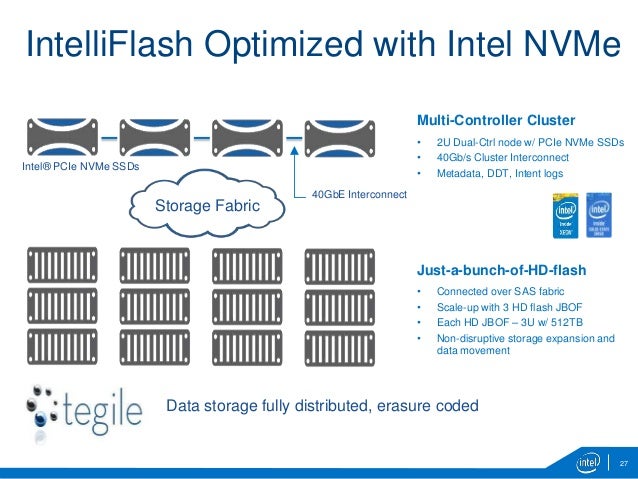
Facebook is announcing its flexible NVMe JBOF (just a bunch of flash), Lightning.
http://www.storagereview.com/facebook_introduces_a_flexible_nvme_jbof

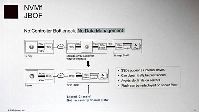
  • "NVMe in a shared chassis look like an internal drive – so it's not shared data. It's not a SAN. You cannot run VMFS (VMware file system) on top of that."
With NVMeF there is a remote direct memory access from a host server to a drive in an NVMeF array.
If you have direct host server access to the array's drives across NVMeF then the array is effectively controller-less, and just a bunch of flash drives (JBOF)
"A SAN? That's associated with Fibre Channel and SCSI. I would call it NVMeF. This is a SAN replacement or next-generation of SAN. It may be a bit confusing to call it a SAN."
https://www.theregister.co.uk/2017/06/23/is_an_nvme_over_fabrics_array_a_san/
  • Is an NVMe over fabrics array a SAN? "NVMe in a shared chassis look like an internal drive – so it's not shared data. It's not a SAN. You cannot run VMFS (VMware file system) on top of that." With NVMeF there is a remote direct memory access from a host server to a drive in an NVMeF array. If you have direct host server access to the array's drives across NVMeF then the array is effectively controller-less, and just a bunch of flash drives (JBOF)
    "A SAN? That's associated with Fibre Channel and SCSI. I would call it NVMeF. This is a SAN replacement or next-generation of SAN. It may be a bit confusing to call it a SAN."


Friday, February 9, 2018

GPT vs MBR && BIOS vs. UEFI


  • UEFI systems require an EFI System Partition.

BIOS systems that are partitioned with GPT require a BIOS boot partition if GRUB is used as the bootloader.
 
GUID Partition Table (GPT) is an alternative, contemporary, partitioning style; it is intended to replace the old Master Boot Record (MBR) system. GPT has several advantages over MBR which has quirks dating back to MS-DOS times. With the recent developments to the formatting tools fdisk (MBR) and gdisk (GPT), it is equally easy to get good dependability and performance for GPT or MBR

If you are partitioning a disk of 2 TiB or larger, you need to use GPT.

https://wiki.archlinux.org/index.php/partitioning


  • Compared with MBR disk, A GPT disk can support larger than 2 TB volumes where MBR cannot.

GPT disks also support up to 128 partitions rather than the 4 primary partitions limited to MBR
GPT keeps a backup of the partition table at the end of the disk. Furthermore, GPT disk provides greater reliability due to replication and cyclical redundancy check (CRC) protection of the partition table


BIOS
The name originated from the Basic Input/Output System used in the CP/M operating system in 1975
The fundamental purposes of the BIOS are to initialize and test the system hardware components, and to load a bootloader or an operating system from a mass memory device.
The BIOS additionally provides abstraction layer for the hardware, i.e. a consistent way for application programs and operating systems to interact with the keyboard, display, and other input/output devices

UEFI
The Unified Extensible Firmware Interface (UEFI)
UEFI is meant to replace the Basic Input/Output System (BIOS) firmware interface


BIOS vs. UEFI
UEFI enables better use of bigger hard drives. Though UEFI supports the traditional master boot record (MBR) method of hard drive partitioning, it doesn't stop there. It's also capable of working with the GUID Partition Table (GPT), which is free of the limitations the MBR places on the number and size of partitions. GPT ups the maximum partition size from 2.19TB to 9.4 zettabytes.

Technical changes abound in UEFI. UEFI has room for more useful and usable features than could ever be crammed into the BIOS. Among these are cryptography, network authentication, support for extensions stored on non-volatile media, an integrated boot manager, and even a shell environment for running other EFI applications such as diagnostic utilities or flash updates. In addition, both the architecture and the drivers are CPU-independent, which opens the door to a wider variety of processors (including those using the ARM architecture, for example).

https://wiki.manjaro.org/index.php?title=Some_basics_of_MBR_v/s_GPT_and_BIOS_v/s_UEFI


  • Traditionally, the system BIOS performs initialization, boot, system management, and configuration tasks. The

BIOS initializes the system’s processors, memory, bus controllers, and I/O devices. After initialization is
complete, the BIOS passes control to operating system (OS) software. The OS loader uses basic services
provided by the system BIOS to locate and load OS modules into system memory. After booting the system,
the BIOS and embedded management controllers execute system management algorithms, which monitor
and optimize the condition of the underlying hardware. BIOS configuration settings enable fine-tuning of the
performance, power management, and reliability features of the system


Comparing UEFI and Traditional BIOS
This sections explains how UEFI corrects certain shortcomings in traditional BIOS implementations. The UEFI
boot mode offers:
 Improved Partitioning scheme for boot media
o Support for media larger than 2 TB
o Redundant partition tables
 Flexible handoff from BIOS to OS
Consolidated firmware user interface
 Enhanced resource allocation for boot device firmware

Partitioning Scheme for Boot Media
Traditional BIOS implementations use the Master Boot Record (MBR) scheme for partitioning boot media.
Because it uses 32-bit addressing and 512-byte blocks, the MBR scheme limits the addressable storage in
the boot media to 2 TB. The MBR scheme also limits the number of partitions to four, and expects bootstrap
code to reside at specific locations in the media.
UEFI defines an improved partitioning scheme known as a GUID Partition Table (GPT). The GPT scheme
uses 64-bit addressing, so the boot media can be much larger than 2 TB. Each entry in the table is identified
by a 128-bit Globally Unique Identifier (GUID), so the scheme supports a large number of partitions. Bootstrap
code is no longer required at fixed locations, and a backup partition table provides redundancy


Handoff from BIOS to Operating System
After performing system initialization, the BIOS attempts to transfer control to an operating system. Traditional
BIOS implementations maintain a prioritized list (“boot order”) of bootable media in the system, and attempt to
launch boot software according to the list of media. For each entry in the list, the BIOS loads bootstrap code
from a well-known location and passes control to it; if the attempt fails, the BIOS attempts subsequent entries
in the list.
UEFI implementations also maintain a boot order, but each entry corresponds to an individual file instead of
an entire bootable medium. This scheme allows for one medium (such as a hard disk) to contain multiple boot
order entries (for example, multiple operating system loaders). Since each entry specifies the location of the
boot file, UEFI also supports booting via Uniform Resource Identifiers (URIs).
Unlike traditional BIOS implementations, all bootable files (executable bootstrap images) must be formatted
according to the Portable Executable / Common Object File Format (PE/COFF). This requirement applies to
any code executed by the BIOS, including device firmware (traditionally called “option ROMs”), pre-boot
execution environment (PXE) boot programs, and operating system loaders


UEFI defines a shared user interface known as the Human Interface Infrastructure (HII). A user can configure
all the firmware settings - including BIOS, onboard management controller, and boot devices – using a single
user interface, without needing a reboot between changes for each device. HII also facilitates remote
configuration of all firmware settings via baseboard management controller interfaces.

Traditional BIOS implementations offer limited memory space for boot device firmware. Boot devices such as
storage controllers and network interface controllers require increasing amounts of memory to execute their
firmware during the boot process. When a system contains multiple boot devices, a traditional BIOS may not
allocate enough memory space for all of the device firmware to execute.
UEFI eliminates this limitation by defining standard interfaces for memory management. In UEFI boot mode,
boot devices use these interfaces to request memory space from the BIOS memory manager. When a system
contains multiple boot devices, UEFI boot mode allocates memory on-demand for each device’s firmware.

Boot Mode Considerations: BIOS vs. UEFI
DELL EMC


  • What is expansion ROM for BIOS ?
The purpose of the BIOS is to initialize the system before calling the boot loader to start the OS.
After completing the motherboard initialization, the BIOS start scanning for option ROM modules (expansion ROM) on the various devices. The expansion ROM includes device-specific initialization code. Once the BIOS identifies a compatible expansion ROM, it will simply call it. After the device specific code is executed, it will return the control back to the BIOS.
What changed with the introduction of UEFI?
Unified Extensible Firmware Interface (UEFI) is replacing and extending the traditional BIOS.
Traditional BIOS does not specify the behavior of the vendor’s code on the expansion ROM, so different vendors may have very different implementation. In contrast, UEFI’s spec clearly defines division of labor between the BIOS itself and the expansion ROMs. The standard defines a variety of functionalities or Services.
Each module manufacturer can implement any subset of these Services, so the behavior becomes uniform across vendors.
Once the UEFI BIOS identifies a compatible expansion ROM, it will use the API as defined in the spec to query the module’s capabilities and utilize the implemented functionalities.
Common functionalities can be implemented by the BIOS itself, e.g. significant parts of PXE boot.
https://community.mellanox.com/docs/DOC-1852

Monday, January 29, 2018

TAP vs SPAN

  • To TAP or SPAN?
(Test Access Point)
A simple hardware device that copies all network  traffic for monitoring, analysis, and security

(Switch Port Analyzer / Mirror)
Software built into switches and routers that copies
selected packets passing through the device

To summarize, here are the top 10 reasons why network TAPs are preferred over SPAN ports:
TAPs create an exact copy of the bi-directional network  traffic at full line rate, providing full fidelity for network monitoring, analytics and security.
https://www.gigamon.com/content/dam/resource-library/english/white-paper/wp-tap-vs-span.pdf

Tuesday, November 28, 2017

Network Address Translation (NAT) and Port Address Translation (PAT)


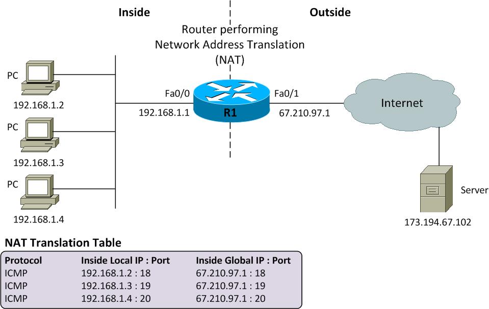
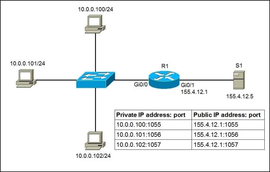
  • Network Address Translation (NAT) and Port Address Translation (PAT) both map IP addresses on an internal network to IP addresses on an external network.


If you are connecting a site in the 10.10.10.0 network to a site in the 10.10.20.0 network, you could use NAT to translate 10.10.10.0 IP addresses to available 10.10.20.0 IP addresses so that hosts on the 10.10.10.0 network can access data and use network resources on the 10.10.20.0 network.
NAT requires a one-to-one relationship when translating IP addresses.

For example, two hosts that have been assigned the IP addresses 10.10.10.100 and 10.10.10.101, respectively, could send traffic to and receive traffic from the Internet by using the single public IP address 123.45.67.89.

PAT is also referred to as NAT overloading because it uses one IP address for all clients to multiple ports, whereas standard NAT uses a one-to-one IP address relationship per client
http://blog.boson.com/bid/53313/NAT-and-PAT-What-s-the-Difference


  • Port Address Translation (PAT) is a feature of a network device
that translates communications made between hosts on a
private network and hosts on a public network.
• PAT allows a single public IP address to be used by many hosts
on the private network, which is usually a LAN.
• Cisco uses term PAT, while other vendors use different names:
— Microsoft: Internet Connection Sharing,
— Check Point: Hide-Mode NAT
• PAT is informally called router; gateway is more appropriate.
• PAT device sits at the network perimeter where one side connects the external network, usually the public Internet, and on
the other side an internal network using private IP addressing.
• PAT operation is typically transparent to both the internal and
external hosts.

When a host in the private network sends its first packet to
some host in the outside network (as either TCP SYN or UDP
segment), the PAT device replaces the inside source IP address
in the IP header with a single public IP.
• Also, it assigns to this connection a port number from the pool
of available ports, inserts this number in the TCP/UDP header
source port, and places the IP packet on the outside network.
• The PAT device then makes an entry in its translation table
containing the inside IP address, TCP or UDP, inside source
port, and assigned outside port.
• Subsequent packets from the same TCP connection on the
inside IP address are always translated to the same outside
port number (and outside IP address).

• The host in the external network receiving a data packet will
move the source IP address and source port as the
corresponding destination fields in any response it sends back.
• For packets arriving from outside, the PAT device operates on
IP destination address and TCP/UDP destination port:
— If the destination port number of the incoming TCP/UDP
segment is not found as an outside port in the translation
table, the IP packet is simple dropped.
— Otherwise, the corresponding inside IP address and inside
port number from the translation table replace, in the
incoming packet, the destination address in IP header and
the destination port in TCP/UDP header.
— And, the modified IP packet is placed on the inside network

A host at IP address 192.168.0.2 on a private network may ask
for TCP connection to a remote host on the public network
giving source address & source port 192.1680.2&15245.
• PAT device, with its public IP address 214.35.3.4, translates
this source address & source port pair to 214.35.3.4 & 16529
(16529 was available in the pool) and make an entry in its
internal table that port 16529 is in use by 192.168.0.2 on the
private network with TCP connection on port number 15245.
• When a packet is received from the public network by the PAT
device with 214.35.3.4&16529, the packet is forwarded to the
internal network with destination IP address changed to
192.168.0.2 and with the port destination changed to 15345.

 Advantages:
— multiple internal hosts can share a single IP address for
communication, thus conserving precious IP addresses,
— hosts on the private network don’t have to exposed their
private IP addresses to the public network, making attacks
from the public network less likely.

Disadvantages:
— an organization using PAT and a single IP address cannot
easily run more than one of the same type of public service
behind a PAT, e.g. two Web public servers using the default
port 80; Also, a remote login is possible on


http://web.cse.ohio-state.edu/~athreya.14/cse3461-5461/Cse3461.NAT-PAT.pdf


  • Port Address Translation
Port Address Translation (PAT) is an extension of Network Address Translation (NAT) that permits multiple devices on a LAN to be mapped to a single public IP address to conserve IP addresses.

PAT is similar to port forwarding except that an incoming packet with destination port (external port) is translated to a packet different destination port (an internal port). The Internet Service Provider (ISP) assigns a single IP address to the edge device. When a computer logs on to the Internet, this device assigns the client a port number that is appended to the internal IP address, giving the computer a unique IP address.

If another computer logs on the Internet, this device assigns it the same public IP address, but a different port number. Although both computers are sharing the same public IP address, this device knows which computer to send its packets, because the device uses the port numbers to assign the packets the unique internal IP address of the computers.
https://www.cisco.com/assets/sol/sb/RV320_Emulators/RV320_Emulator_v1-1-0-09/help/Setup13.html