Josh Bloch: I like to ask a candidate to solve a small-scale design problem, finger exercises, to see how they think and what their process is: "How would you write a function that tells me if its argument is a power of 2?" I'm not looking for the optimal bit-twiddling solution ((n & -n) == n). I'm looking to see if they get the method signature right, if they think about boundary cases, if their algorithm is reasonable and they can explain its workings, and if they can improve on their first attempt.
Hamming codes are used to insert error correction information into data streams. The codes are designed so that an error can not only be detected, but corrected. Adding error correction information increases the amount of data, but increases the reliability of communications over mediums with high error rates
Hamming distance of two bit strings = number of bit positions in which they differ
If the valid words of a code have minimum Hamming distance D, then D-1 bit errors can be detected.
If the valid words of a code have minimum Hamming distance D, then [(D-1)/2] bit errors can be corrected.
The Hamming Distance is a number used to denote the difference between two binary strings.
Hamming's formulas allow computers to detect and correct error on their own.
The Hamming Code earned Richard Hamming the Eduard Rheim Award of Achievement in Technology in 1996, two years before his death
Hamming's additions to information technology have been used in such innovations as modems and compact discs.
Step 1
Ensure the two strings are of equal length. The Hamming distance can
only be calculated between two strings of equal length. String 1: "1001
0010 1101" String 2: "1010 0010 0010"
Step 2
Compare the first two bits in each string. If they are the same, record a
"0" for that bit. If they are different, record a "1" for that bit. In
this case, the first bit of both strings is "1," so record a "0" for the
first bit.
Step 3
Compare each bit in succession and record either "1" or "0" as
appropriate. String 1: "1001 0010 1101" String 2: "1010 0010 0010"
Record: "0011 0000 1111"
Step 4
Add all the ones and zeros in the record together to obtain the Hamming distance. Hamming distance = 0+0+1+1+0+0+0+0+1+1+1+1 = 6
The Hamming Distance can be used to correct or detect errors in a transmission.
If there are d errors, you need a Hamming Distance of 2d+1 to correct or d+1 to detect.
Hamming distance between two vectors is the number of bits we must change to change one into the other.
Example Find the distance between the vectors 01101010 and 11011011.
01101010
11011011
They differ in four places, so the Hamming distance d(01101010; 11011011) = 4.
SYSVOL Replication Migration Guide: FRS to DFS Replication
Domain controllers use a special shared folder named SYSVOL to replicate logon scripts and Group Policy object files to other domain controllers. Windows 2000 Server and Windows Server 2003 use File Replication Service (FRS) to replicate SYSVOL, whereas Windows Server 2008 uses the newer DFS Replication service when in domains that use the Windows Server 2008 domain functional level, and FRS for domains that run older domain functional levels.
http://technet.microsoft.com/en-us/library/dd640019%28v=ws.10%29.aspx
Database mirroring is a solution for increasing the availability of a SQL Server database. Mirroring is implemented on a per-database basis and works only with databases that use the full recovery model.
automatic failover
The process by which, when the principal server becomes unavailable, the mirror server to take over the role of principal server and brings its copy of the database online as the principal database.
High-performance mode
The database mirroring session operates asynchronously and uses only the principal server and mirror server. The only form of role switching is forced service (with possible data loss).
High-safety mode
The database mirroring session operates synchronously and, optionally, uses a witness, as well as the principal server and mirror server.
mirror database
The copy of the database that is typically fully synchronized with the principal database.
principal database
In database mirroring, a read-write database whose transaction log records are applied to a read-only copy of the database (a mirror database).
Witness
For use only with high-safety mode, an optional instance of SQL Server that enables the mirror server to recognize when to initiate an automatic failover. Unlike the two failover partners, the witness does not serve the database. Supporting automatic failover is the only role of the witness.
Group Policy slow link detection
Defines a slow connection for purposes of applying and updating Group Policy.
If the rate at which data is transferred from the domain controller providing a policy update to the computers in this group is slower than the rate specified by this policy, the system considers the connection to be slow.
If you disable this policy or do not configure it, the system uses the default value of 500 kilobits per second.
Routing Information Protocol (RIP),
Open Shortest Path First (OSPF),
Enhanced Interior Gateway Protocol (EIGRP, Cisco proprietary protocol),
Intermediate System to Intermediate System (IS-IS).
Exterior Gateway Protocols (currently there is only one in use)
Once upon a time, when the Internet was just a tiny cloud, there were only a few networks connected to each other
All that needed to be done to set up routing was to define network nodes and make connections between them as needed.
As we all know, the Internet didn’t stay small for very long.
It began to incorporate more and more networks, which necessitated a more dynamic routing system.
EGP (External Gateway Protocol) was invented to do the job.
In modern networks, tree topologies were replaced by fully connected mesh topologies to allow for maximum scalability.
The Emergence of Autonomous System Architecture
As the Internet continued to expand, it became increasingly difficult to keep track of all the routes from one network to another.
The solution was to transition to an Autonomous System (AS) architecture
An AS can be an Internet Service Provider, a university or an entire corporate network, including multiple locations (IP addresses).
Each AS is represented by a unique number called an ASN.
each autonomous system controls a collection of connected routing prefixes, representing a range of IP addresses
It then determines the routing policy inside the network.
As the number of autonomous systems in the internet grew, the drawbacks of EGP became more pronounced.
Its hierarchical structure hampered scalability and made it difficult to connect new networks in an efficient manner.
it was necessary to define a new exterior routing protocol that would provide enhanced and more scalable capabilities.
BGP is Just Like GPS for Packets
You can think of an autonomous system in the computer world as a city with many streets. A network prefix is similar to one street with many houses. An IP address is like an address for a particular house in the real world, while a packet is the equivalent of a car travelling from one house to another using the best possible route.
BGP is designed to exchange routing and reachability information between autonomous systems on the Internet.
Each BGP speaker, which is called a “peer”, exchanges routing information with its neighboring peers in the form of network prefix announcements. This way, an AS doesn’t need to be connected to another AS to know its network prefix.
Each peer manages a table with all the routes it knows for each network and propagates that information to its neighboring autonomous systems.
In this way, BGP allows an AS to collect all the routing information from its neighboring autonomous systems and “advertise” that information further.
Each peer transfers the information internally inside its own autonomous system.
https://www.incapsula.com/blog/bgp-routing-explained.html
MicroNugget: What is BGP and How Does it Work?
The routing protocol of the internet
management of trust and untrust
the slowest routing protocol in the world
service providers use BGP,or enterprise level customers
Static routing
Static routes are one way we can communicate to remote networks. In production networks, static routes are mainly configured when routing from a particular network to a stub network.
stub networks are networks that can only be accessed through one point or one interface.
There are three routing table principles that dictate how routers communicate.
“routers forward packets based on information contained in their routing tables ONLY.”
” Routing information on one router does not mean that other routers in the domain have the same information.”
“Routes on a router to a remote network do not mean that the remote router has return paths.”
http://www.ccnablog.com/static-routing/
Dynamic routing protocols
Classification
Dynamic routing protocols can be classified in several ways.
Interior and exterior gateway routing protocols,
Distance vector, path vector and link state routing protocols,
Classful and classless.
Routing protocols function by:
Discovering remote networks
Maintaining current routing information
Path determination
Disadvantages
Require more expertise by the administrator, they are not as simple to configure as static routes.
They use more of the routers resources; such as CPU and RAM.
routing protocols fall into two main categories which are;
EGP – Exterior Gateway Protocols
IGP – Interior Gateway Protocols
Autonomous systems also known as routing domains; are collections of routers under the same administration. This may mean the routers that are owned by one company.
Interior Gateway Protocols (IGP) are used for intra-autonomous system routing – routing inside an autonomous system.
Exterior Gateway Protocols (EGP) are used for inter-autonomous system routing – routing between autonomous systems.
Egp vs igp
Interior Gateway Protocols (IGPs) can be classified as two types:
Distance vector routing protocols
Link-state routing protocols
Distance vector routing protocols vs. link state routing protocols
Distance vector protocols work best in situations where:
The network is simple and flat and does not require a special hierarchical design.
The administrators do not have enough knowledge to configure and troubleshoot link-state protocols.
Specific types of networks, such as hub-and-spoke networks, are being implemented.
Worst-case convergence times in a network are not a concern
Link state routing protocols usually have a complete view of the topology. They usually know of the best paths as well as backup paths to networks. Link state protocols use the shortest-path first algorithm to find the best path to a network.
Link-state protocols work best in situations where:
The network design is hierarchical, usually occurring in large networks.
The administrators have a good knowledge of the implemented link-state routing protocol.
Fast convergence of the network is crucial.
Classful and classless
Classful Routing Protocols
Since they do not include the subnet mask in their routing updates, they cannot work where the networks have been subnetted.
Classless routing protocols
Classless routing protocols include the subnet mask with the network address in routing updates.
Metric
The metric, is the mechanism used by the routing protocol to assign costs to reach remote networks
The metric is used to determine the best path to a network when there are multiple paths.
Administrative distance
The administrative distance is the way routers use to give preference to routing sources. For example if a router learns of the same route via EIGRP and RIP, it will prefer the route it learnt via EIGRP.
The AD is usually a value from 0 to 255, the lower the value the better the routing source, a route with an administrative distance of 255 will never be trusted.
To provide for fault tolerance, many networks implement redundant paths between devices using multiple switches. However, providing redundant paths between segments causes packets to be passed between the redundant paths endlessly. This condition is known as a bridging loop.
(Note: the terms bridge, switch are used interchangeably when discussing STP)
To prevent bridging loops, the IEEE 802.1d committee defined a standard called the spanning tree algorithm (STA), or spanning tree protocol (STP). Spanning-Tree Protocol is a link management protocol that provides path redundancy while preventing undesirable loops in the network. For an Ethernet network to function properly, only one active path can exist between two stations.
How Spanning Tree Protocol (STP) works
SPT must performs three steps to provide a loop-free network topology:
1. Elects one root bridge
2. Select one root port per nonroot bridge
3. Select one designated port on each network segment
when turned on, each switch claims itself as the root bridge immediately and starts sending out multicast frames called Bridge Protocol Data Units (BPDUs), which are used to exchange STP information between switches.
https://www.9tut.com/spanning-tree-protocol-stp-tutorial
Rapid Spanning Tree Protocol RSTP Tutorial
One big disadvantage of STP is the low convergence which is very important in switched network. To overcome this problem, in 2001, the IEEE with document 802.1w introduced an evolution of the Spanning Tree Protocol: Rapid Spanning Tree Protocol (RSTP), which significantly reduces the convergence time after a topology change occurs in the network. While STP can take 30 to 50 seconds to transit from a blocking state to a forwarding state, RSTP is typically able to respond less than 10 seconds of a physical link failure.
http://www.9tut.com/rapid-spanning-tree-protocol-rstp-tutorial
Ethernet Automatic Protection Switching Overview
Ethernet automatic protection switching (APS) is a linear protection scheme designed to protect VLAN based Ethernet networks.
With Ethernet APS, a protected domain is configured with two paths, a working path and a protection path. Both working and protection paths can be monitored using an Operations Administration Management (OAM) protocol like Connectivity Fault Management (CFM). Normally, traffic is carried on the working path (that is, the working path is the active path), and the protection path is disabled. If the working path fails, its protection status is marked as degraded (DG) and APS switches the traffic to the protection path, then the protection path becomes the active path.
https://www.juniper.net/documentation/en_US/junos/topics/concept/ethernet-automatic-protection-switching-overview.html
VRRP, the Virtual Router Redundancy Protocol, explained by Juniper Engineers
multicast IP packet
destination IP address is multicast not unicast, group of IPs,not a single IP
source IP address is unicast
IPv4 multicast address
all has first 3 bits set to 1
unlike unicast there is not a protocol to map IP addresses to MAC addresses
all multicast MAC addresses has last bit of first octet set to 1.
Open Standard means VRRP can be configured on any vendor
VRRP Roles
Master/Active
Backup/Standby
VRRP encapsulated in IP protocol No:112
VRRP supports two types of authentication; plaintext and MD5
VRRP MAC;0000.5e00.01XX ; XX is groupid
Quagga is a network routing software suite providing implementations of Open Shortest Path First (OSPF), Routing Information Protocol (RIP), Border Gateway Protocol (BGP) and IS-IS for Unix-like platforms, particularly Linux, Solaris, FreeBSD and NetBSD
https://en.wikipedia.org/wiki/Quagga_(software)
an autonomous system (AS) is a large network or group of networks that has a unified routing policy. Every computer or device that connects to the Internet is connected to an AS.
An autonomous system (AS) is a collection of routers under a common administration such as a company or an organization. An AS is also known as a routing domain. Typical examples of an AS are a company’s internal network and an ISP’s network.
What Does External Border Gateway Protocol (EBGP) Mean?
External Border Gateway Protocol (EBGP) is a Border Gateway Protocol (BGP) extension that is used for communication between distinct autonomous systems (AS). EBGP enables network connections between autonomous systems and autonomous systems implemented with BGP.
We need EBGP between AS1 and AS2 because these are two different autonomous systems. This allows us to advertise a prefix on R1 in BGP so that AS2 can learn it.
We also need EBGP between AS2 and AS3 so that R5 can learn prefixes through BGP.
So that’s the first reason why we need IBGP…so you can advertise a prefix from one autonomous system to another.
Border Gateway Protocol (BGP) is a standardized exterior gateway protocol designed to exchange routing and reachability information among autonomous systems (AS) on the Internet.[2] BGP is classified as a path-vector routing protocol,[3] and it makes routing decisions based on paths, network policies, or rule-sets configured by a network administrator.
BGP used for routing within an autonomous system is called Interior Border Gateway Protocol, Internal BGP (iBGP). In contrast, the Internet application of the protocol is called Exterior Border Gateway Protocol, External BGP (eBGP).
Spanning Tree Protocol (STP) is a communication protocol operating at data link layer the OSI model to prevent bridge loops and the resulting broadcast storms
In case a particular active link fails, the algorithm is executed again to find the minimal spanning tree without the failed link. The communication continues through the newly formed spanning tree. When a failed link is restored, the algorithm is re-run including the newly restored link.
By default Cisco Catalyst Switches run PVST+ or Rapid PVST+ (Per VLAN Spanning Tree). This means that each VLAN is mapped to a single spanning tree instance. When you have 20 VLANs, it means there are 20 instances of spanning tree.
MST works with the concept of regions. Switches that are configured to use MST need to find out if their neighbors are running MST.
Listening state: Only a root or designated port will move to the listening state. The non-designated port will stay in the blocking state.No data transmission occurs at this state for 15 seconds just to make sure the topology doesn’t change in the meantime. After the listening state we move to the learning state.
Learning state: At this moment the interface will process Ethernet frames by looking at the source MAC address to fill the mac-address-table. Ethernet frames however are not forwarded to the destination. It takes 15 seconds to move to the next state called the forwarding state.
Forwarding state: This is the final state of the interface and finally the interface will forward Ethernet frames so that we have data transmission!
With STP, the key is for all the switches in the network to elect a root bridge that becomes the focal point in the network. All other decisions in the network, such as which port to block and which port to put in forwarding mode, are made from the perspective of this root bridge. A switched environment, which is different from a bridge environment, most likely deals with multiple VLANs. When you implement a root bridge in a switching network, you usually refer to the root bridge as the root switch. Each VLAN must have its own root bridge because each VLAN is a separate broadcast domain
OSPF is an interior gateway protocol (IGP) that routes packets within a single autonomous system (AS). OSPF uses link-state information to make routing decisions, making route calculations using the shortest-path-first (SPF) algorithm (also referred to as the Dijkstra algorithm). Each router running OSPF floods link-state advertisements throughout the AS or area that contain information about that router’s attached interfaces and routing metrics.
This document describes the Open Shortest Path First Version 3 (OSPFv3) Autonomous System (AS) External Link State Advertisement (LSA) Type 5 route selection mechanism. It presents a network scenario with the configuration for how to select the route received from one Autonomous System Boundary Router (ASBR) over another.
MPLS operates at a layer that is generally considered to lie between traditional definitions of OSI Layer 2 (data link layer) and Layer 3 (network layer), and thus is often referred to as a layer 2.5 protocol
Why VPWS service - MPLS has a two ethernet frame headers?
the encapsulation is removed and the original frame is sent to the local network.
The outer label is used for switching within the MPLS tunnel. The inner label is ignored while in the tunnel - currently, it's just payload to transport.
Once the encapsulated payload reaches the destination network, the encapsulation is removed and the original frame continues on as before the tunnel.
As packets travel through the MPLS network, their labels are switched or swapped.
The packet enters the edge of the MPLS backbone, is examined, classified and given an appropriate label, and forwarded to the next hop in the pre-set Label Switched Path (LSP). As the packet travels that path, each router on the path uses the label – not other information, such as the IP header – to make the forwarding decision that keeps the packet moving along the LSP.
However, within each router, the incoming label is examined and its next hop is matched with a new label. The old label is replaced with the new label for the packet’s next destination, and then the freshly labeled packet is sent to the next router. Each router repeats the process until the packet reaches an egress router.
The label information is removed at either the last hop or the exit router, so that the packet goes back to being identified by an IP header instead of an MPLS label.
When an IP packet arrives at a router (Rosen et al., 2001) the next hop for this packet is determined by the routing algorithm in operation, which uses the longest prefix match
“Border Gateway Protocol (BGP) is a standardized exterior gateway protocol designed to exchange routing and reachability information between autonomous systems (AS) on the Internet.
While processing the header, the router compares the destination IP address, bit-by-bit, with the entries in the routing table.
The entry that has the longest number of network bits that match the IP destination address is always the best match (or best path) as shown in the following example:
A switch dynamically builds its MAC address table by examining the source MAC addresses of the frames received on a port. The switch forwards frames by searching for a match between the destination MAC address in a frame and an entry in the MAC address table.
If the destination IP address and the subnet mask do not match, the entries in the routing table are compared to the destination IP address. If a match is found (i.e., the destination IP address and the subnet mask AND to a value found in the routing table), the packet is sent to the gateway listed in the routing table. If no matching entries can be found, the packet is sent to the defined default gateway
A switching loop or bridge loop occurs in computer networks when there is more than one Layer 2 (OSI model) path between two endpoints (e.g. multiple connections between two network switches or two ports on the same switch connected to each other). The loop creates broadcast storms as broadcasts and multicasts are forwarded by switches out every port, the switch or switches will repeatedly rebroadcast the broadcast messages flooding the network. Since the Layer 2 header does not support a time to live (TTL) value, if a frame is sent into a looped topology, it can loop forever
How do I stop a network loop?
A physical topology that contains switching or bridge loops is attractive for redundancy reasons, yet a switched network must not have loops. The solution is to allow physical loops, but create a loop-free logical topology using the shortest path bridging (SPB) protocol or the older spanning tree protocols (STP) on the network switches
A switching loop or bridge loop occurs in computer networks when there is more than one layer 2 path between two endpoints (e.g. multiple connections between two network switches or two ports on the same switch connected to each other). The loop creates broadcast storms as broadcasts and multicasts are forwarded by switches out every port, the switch or switches will repeatedly rebroadcast the broadcast messages flooding the network.[1] Since the layer-2 header does not include a time to live (TTL) field, if a frame is sent into a looped topology, it can loop forever.
A physical topology that contains switching or bridge loops is attractive for redundancy reasons, yet a switched network must not have loops. The solution is to allow physical loops, but create a loop-free logical topology using link aggregation, shortest path bridging, spanning tree protocol or TRILL on the network switches.
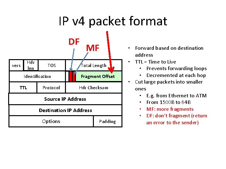
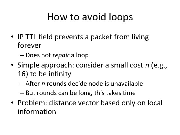
Routing loops are tempered by a time to live (TTL) field in layer-3 packet header; Packets will circulate the routing loop until their TTL value expires. No TTL concept exists at layer 2 and packets in a switching loop will circulate until dropped, e.g. due to resource exhaustion.
https://en.wikipedia.org/wiki/Switching_loop
Broadcast storm
Most commonly the cause is a switching loop in the Ethernet network topology (i.e. two or more paths exist between switches). As broadcasts and multicasts are forwarded by switches out of every port, the switch or switches will repeatedly rebroadcast broadcast messages and flood the network. Since the layer-2 header does not support a time to live (TTL) value, if a frame is sent into a looped topology, it can loop forever.
In some cases, a broadcast storm can be instigated for the purpose of a denial of service (DOS) using one of the packet amplification attacks, such as the smurf attack or fraggle attack, where an attacker sends a large amount of ICMP Echo Requests (ping) traffic to a broadcast address, with each ICMP Echo packet containing the spoof source address of the victim host
In wireless networks a disassociation packet spoofed with the source to that of the wireless access point and sent to the broadcast address can generate a disassociation broadcast DOS attack
Prevention
Switching loops are largely addressed through link aggregation, shortest path bridging or spanning tree protocol. In Metro Ethernet rings it is prevented using the Ethernet Ring Protection Switching (ERPS) or Ethernet Automatic Protection System (EAPS) protocols.
Filtering broadcasts by Layer 3 equipment, typically routers (and even switches that employ advanced filtering called brouters).
Physically segmenting the broadcast domains using routers at Layer 3 (or logically with VLANs at Layer 2) in the same fashion switches decrease the size of collision domains at Layer 2.
Routers and firewalls can be configured to detect and prevent maliciously inducted broadcast storms (e.g. due to a magnification attack).
Broadcast storm control is a feature of many managed switches in which the switch intentionally ceases to forward all broadcast traffic if the bandwidth consumed by incoming broadcast frames exceeds a designated threshold. Although this does not resolve the root broadcast storm problem, it limits broadcast storm intensity and thus allows a network manager to communicate with network equipment to diagnose and resolve the root problem.
Apache Struts 2 is an elegant, extensible framework for creating enterprise-ready Java web applications. The framework is designed to streamline the full development cycle, from building, to deploying, to maintaining applications over time.
Apache Struts 2 was originally known as WebWork 2. After working independently for several years, the WebWork and Struts communities joined forces to create Struts2. This new version of Struts is simpler to use and closer to how Struts was always meant to be.
NULLIF Function
In Oracle/PLSQL, the NULLIF function compares expr1 and expr2. If expr1 and expr2 are equal, the NULLIF function returns NULL. Otherwise, it returns expr1.
http://www.techonthenet.com/oracle/functions/nullif.php
NVL Function
In Oracle/PLSQL, the NVL function lets you substitute a value when a null value is encountered.
http://www.techonthenet.com/oracle/functions/nvl.php
The Oracle DUAL table
dual is a table which is created by oracle along with the data dictionary. It consists of exactly one column whose name is dummy and one record. The value of that record is X.
http://www.adp-gmbh.ch/ora/misc/dual.html
DDL
Data Definition Language (DDL) statements are used to define the database structure or schema. Some examples:
CREATE - to create objects in the database
ALTER - alters the structure of the database
DROP - delete objects from the database
TRUNCATE - remove all records from a table, including all spaces allocated for the records are removed
COMMENT - add comments to the data dictionary
RENAME - rename an object
DML
Data Manipulation Language (DML) statements are used for managing data within schema objects. Some examples:
SELECT - retrieve data from the a database
INSERT - insert data into a table
UPDATE - updates existing data within a table
DELETE - deletes all records from a table, the space for the records remain
MERGE - UPSERT operation (insert or update)
CALL - call a PL/SQL or Java subprogram
EXPLAIN PLAN - explain access path to data
LOCK TABLE - control concurrency
DCL
Data Control Language (DCL) statements. Some examples:
GRANT - gives user's access privileges to database
REVOKE - withdraw access privileges given with the GRANT command
TCL
Transaction Control (TCL) statements are used to manage the changes made by DML statements. It allows statements to be grouped together into logical transactions.
COMMIT - save work done
SAVEPOINT - identify a point in a transaction to which you can later roll back
ROLLBACK - restore database to original since the last COMMIT
SET TRANSACTION - Change transaction options like isolation level and what rollback segment to use
ICMP Destination Unreachable
The Destination Unreachable message is an ICMP message which is generated by the host or its inbound gateway to inform the client that the destination is unreachable for some reason. A Destination Unreachable message may be generated as a result of a TCP, UDP or another ICMP transmission. Unreachable TCP ports notably respond with TCP RST rather than a Destination Unreachable type 3 as might be expected.
http://en.wikipedia.org/wiki/ICMP_Destination_Unreachable
IP-Lookup
Every machine that is on a TCP/IP network ( a local network, or the Internet ) has a unique Internet Protocol ( IP ) address.
IP-Lookup helps you to find information about your current IP address or any other IP address. It supports both IPv4 and IPv6 addresses.
Basically negative float is the amount of
time the project is behind, as determined by the total time for the
tasks on the critical path exceeding the time available for the project.
There is only zero or negative float on the critical path; by
definition the critical path doesn't have positive float. Negative
float is something you want to fix. http://www.projectmanagementquestions.com/2538/when-to-use-a-negative-float
LVM is a logical volume manager for the Linux kernel; it manages disk drives and similar mass-storage devices
LVM is suitable for:
Managing large hard disk farms by letting you add disks, replace disks, copy and share contents from one disk to another without disrupting service (hot swapping)
On small systems (like a desktop at home), instead of having to estimate at installation time how big a partition might need to be in the future, LVM allows you to resize your disk partitions easily as needed.
Making backups by taking "snapshots".
Creating single logical volumes of multiple physical volumes or entire hard disks (somewhat similar to RAID 0, but more similar to JBOD), allowing for dynamic volume resizing.
It might be acceptible to think of this as a sort of virtual disk that you can partition up
You might notice that above the volume group, we have created logical volumes, which might be thought of as virtual partitions, and it is upon these that we build our file systems.
The best analogy I can come up with for explaining LVM is a SAN.
If you've ever used a SAN (Storage Area Network) in your server environment, you know it abstracts the idea of individual hard drives and allows you to carve out "chunks" of space to use as drives.
Rather than worrying about how big your hard drives might be, a SAN lets you throw all your hard drives into a big chassis and then allocate space to individual clients without being concerned about how many or how few physical drives are being used.
LVM is sort of like that, but for an individual system rather than an entire network.
Need a great big partition, but have only a bunch of smaller disks? No problem.
Have only a couple disks now, but want to add more later without reformatting? No problem.
Need to take snapshots, like with virtual servers, but you're using actual bare metal? No problem.
LVM makes dealing with storage far better than partitioning drives or using a simple RAID setup
What LVM Isn't
LVM would be a perfect replacement for hardware- or software-based RAID.
LVM doesn't provide any options for redundancy or parity.
That means if you have a drive fail in LVM, you lose data.
There's no such thing as striped LVM or mirrored LVM; it's simply not designed to do that.
LVM also isn't designed to increase speed by striping reads and writes across multiple disks.
LVM is really cool, but it is not in any way a replacement for RAID.
although it's certainly possible to use a physical drive as a physical volume in LVM, it's not a requirement.
In fact, it's not even the most common scenario.
In most production environments, LVM is used in combination with RAID.
Whether that's hardware-based RAID or software-based RAID, having your underlying physical volumes exist as RAID devices is ideal.
Even if you're installing only onto a single, non-RAID hard drive, setting up LVM allows you flexibility and expansion opportunity later.
Heck, it's possible to add RAID to a server later on, then simply migrate the data from your original physical volume to the RAID physical volume.
in this little example, you've done nothing but create a JBOD (Just a Bunch Of Disks) type system.
The Logical Volume Manager is a system that abstracts storage devices.
LVM supports mirrored volumes. When you create a mirrored logical volume, LVM ensures that data written to an underlying physical volume is mirrored onto a separate physical volume. With LVM, you can create mirrored logical volumes with multiple mirrors.
https://access.redhat.com/documentation/en-US/Red_Hat_Enterprise_Linux/4/html/Cluster_Logical_Volume_Manager/mirrored_volumes.html
The mdadm utility can be used to create and manage storage arrays using Linux's software RAID capabilities.
What's LVM?
What LVM lets you do is collect all your disks, raid arrays and what-not into a big 'box' of storage (called a volume group)
Why not just use LVM?
LVM only lets you mirror or stripe - we want resilience but mirroring is bad - we need to buy twice as much storage as we want
https://www.mythtv.org/wiki/LVM_on_RAID
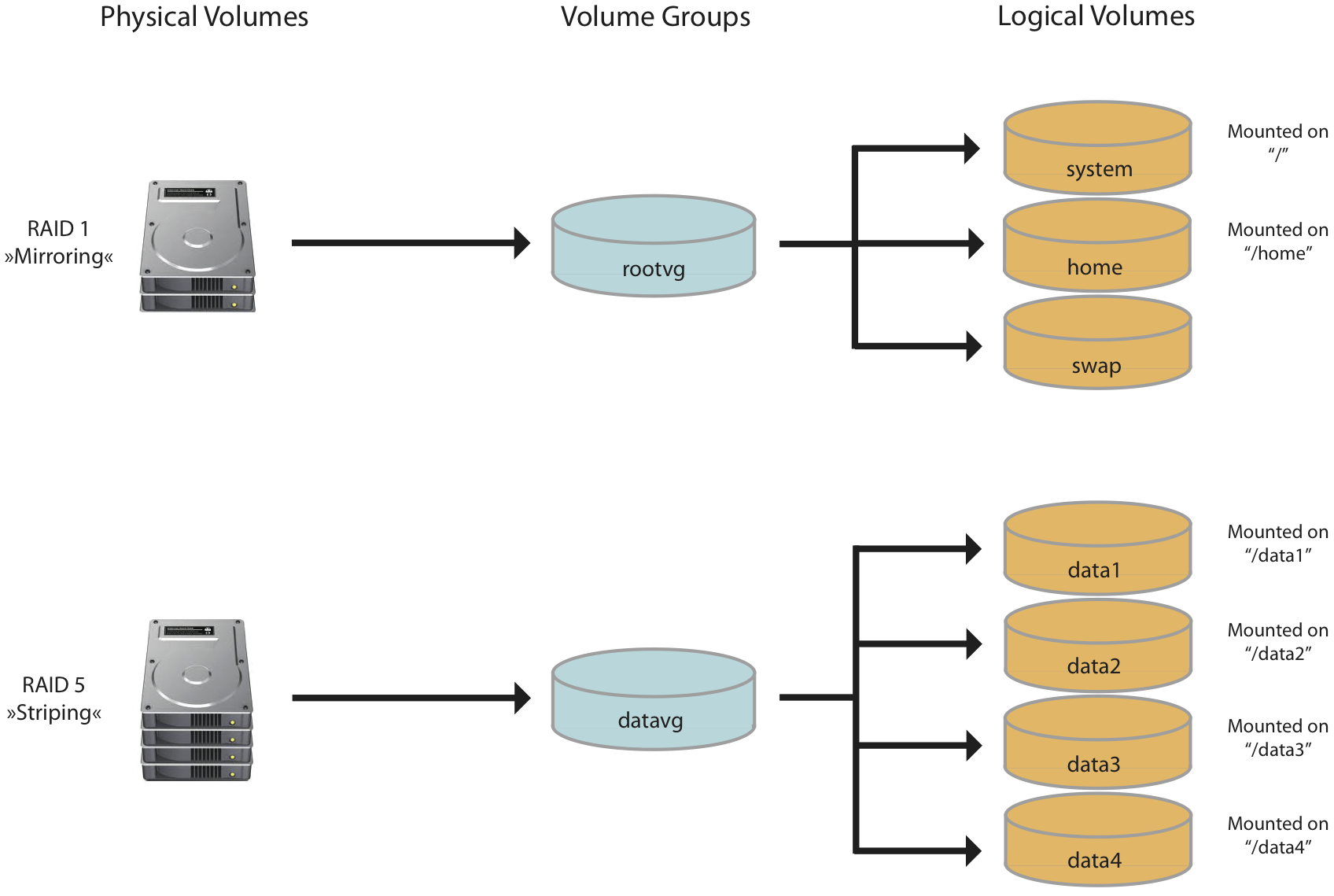
Physical volumes represent disks that have been assigned to a volume group.
All disks or RAID combined disks are managed by LVM. Disks are called physical volumes if used with LVM.
LVM uses each disk directly as a physical volume to overcome limitations and to allow increasing existing disks, which can be done in the hypervisor.
The illustration below shows a RAID 5 (with disk fail protection) which is included as a physical volume into the “datavg” volume group, and on the right hand the file systems “/data1” … “/data4” which use storage space from “datavg”.
The following tutorial is intended to walk you through configuring a RAID 1 mirror using two drives with Mdadm and then configuring LVM on top of that mirror with the XFS file system. This is a great way to begin the setup of a NAS media server for either home or Enterprise use
JDO is - a persistence technology -allows you to create POJOs (plain old java objects) and persist them to the database
If you are an application programmer, you can use JDO technology to directly store your Java domain model instances into the persistent store (database). Alternatives to JDO include direct file I/O, serialization, JDBC, Enterprise JavaBeans (EJB), Bean-Managed Persistence (BMP) or Container-Managed Persistence (CMP) entity beans, and the Java Persistence API.
Java Data Objects (JDO) is a specification of Java object persistence. One of its features is a transparency of the persistence services to the domain model. JDO persistent objects are ordinary Java programming language classes (POJOs
persistence has been "broken out" of "EJB3 Core", and a new standard formed, the Java Persistence API (JPA). JPA uses the javax.persistence package
Significantly, javax.persistence will not require an EJB container, and thus will work within a Java SE environment as well, as JDO always has. JPA, however, is an object-relational mapping (ORM) standard, while JDO is both an object-relational mapping standard and a transparent object persistence standard
JDO, from an API point of view, is agnostic to the technology of the underlying datastore, whereas JPA is targeted to RDBMS datastores (although there are several JPA providers that support access to non-relational datastores through the JPA API, such as DataNucleus and ObjectDB)
http://en.wikipedia.org/wiki/Java_Data_Objects
Apache JDO Java Data Objects (JDO) is a standard way to access persistent data in databases, using plain old Java objects (POJO) to represent persistent data
The approach separates data manipulation (done by accessing Java data members in the Java domain objects) from database manipulation (done by calling the JDO interface methods).
Many enterprise Java developers use lightweight persistent objects provided by open-source frameworks or Data Access Objects instead of entity beans: entity beans and enterprise beans had a reputation of being too heavyweight and complicated, and one could only use them in Java EE application servers. Many of the features of the third-party persistence frameworks were incorporated into the Java Persistence API, and as of 2006 projects like Hibernate (version 3.2) and Open-Source Version TopLink Essentials have become implementations of the Java Persistence API.
JPA is really a specification
Hibernate provides an implementation of the JPA specification. Vendors providing EJB3.0 containers will also be providing an implementation of the JPA spec, so that means Sun and IBM WebSphere and Oracle and all the other handsome players in the industry will provide an implementatio
http://www.coderanch.com/t/218819/ORM/databases/Hibernate-vs-JPA
What is JPA?
JPA is a framework for managing relational data for Java. It can be used with applications utilizing JSE (Java Platform, Standard Edition) or JEE (Java Platform, Enterprise Edition). Its current version is JPA 2.0, which was released on 10 Dec, 2009. JPA replaced EJB 2.0 and EJB 1.1 entity beans (which were heavily criticized for being heavyweight by the Java developer community). Although entity beans (in EJB) provided persistence objects, many developers were used to utilizing relatively lightweight objects offered by DAO (Data Access Objects) and other similar frameworks instead. As a result, JPA was introduced, and it captured many of the neat features of the frameworks mentioned above
What is Hibernate?
Hibernate is a framework that can be used for object-relational mapping intended for Java programming language. More specifically, it is an ORM (object-relational mapping) library that can be used to map object-relational model in to conventional relational model. In simple terms, it creates a mapping between Java classes and tables in relational databases, also between Java to SQL data types. Hibernate can also be used for data querying and retrieving by generating SQL calls. Therefore, the programmer is relieved from the manual handling of result sets and converting objects. Hibernate is released as a free and open source framework distributed under GNU license. An implementation for JPA API is provided in Hibernate 3.2 and later versions.
What is the difference between JPA and Hibernate?
JPA is a framework for managing relational data in Java applications, while Hibernate is a specific implementation of JPA (so ideally, JPA and Hibernate cannot be directly compared). In other words, Hibernate is one of the most popular frameworks that implements JPA. Hibernate implements JPA through Hibernate Annotation and EntityManager libraries that are implemented on top of Hibernate Core libraries. Both EntityManager and Annotations follow the lifecycle of Hibernate. The newest JPA version (JPA 2.0) is fully supported by Hibernate 3.5. JPA has the benefit of having an interface that is standardized, so the developer community will be more familiar with it than Hibernate. On the other hand, native Hibernate APIs can be considered more powerful because its features are a superset of that of JPA.
A prepared statement performs the following checks:
Makes sure that the tables and columns exist
Makes sure that the parameter types match their columns
Parses the SQL to make sure that the syntax is correct
Compiles and caches the compiled SQL so it can be re-executed without repeating these steps
The prepared statement concept is not specific to Java, it is a database concept. Statement precompiling means: when you execute a SQL query, database server will prepare a execution plan before executing the actual query, this execution plan will be cached at database server for further execution.
The advantages of Prepared Statements are:
As the execution plan get cached, performance will be better.
It is a good way to code against SQL Injection as escapes the input values.
When it comes to a Statement with no unbound variables, the database is free to optimize to its full extent. The individual query will be faster, but the down side is that you need to do the database compilation all the time, and this is worse than the benefit of the faster query.
total 1600 drwx---s-x 11 picard STAFF 1536 Jun 26 14:49 . dr-xr-sr-x1300 bin bin 20480 Jun 26 12:06 ..
-rw------- 1 picard STAFF 948 Jun 06 09:46 .addressbook
-rw------- 1 picard STAFF 3368 Jun 06 09:46 .addressbook.lu
-rw------- 1 picard STAFF 193 Apr 02 10:06 .article
-rw------- 1 picard STAFF 1035 May 20 12:30 .bash_history drwx---S-- 2 picard STAFF 512 Jun 23 13:56 .mailpgp
-rw------- 1 picard STAFF 128654 Jun 10 19:19 .newsrc drwx------ 4 picard STAFF 512 May 29 07:01 .pgp
-rw------- 1 picard STAFF 10196 Jun 26 14:33 .pinerc
-rwxr-xr-x 1 picard STAFF 1047 May 27 14:15 .plan
-rw------- 1 picard STAFF 35 Jun 17 09:23 .profile
-rw------- 1 picard STAFF 371 Sep 08 1995 .signature
-rw------- 1 picard STAFF 81691 Jun 20 10:34 3dtree.jpg
-rw------- 1 picard STAFF 31156 Jan 03 10:19 HTMLBgnrGuide.txt drwx---s-x 2 picard STAFF 512 Apr 01 13:26 News
-rw------- 1 picard STAFF 11760 Jul 23 1995 TUTORIAL
-rw------- 1 picard STAFF 234 Feb 02 08:18 baen.txt drwx---s-x 2 picard STAFF 512 Mar 12 06:57 bin
-rw------- 1 picard STAFF 71 Jul 31 1995 calendar
-rw------- 1 picard STAFF 338912 May 02 1995 command.memos
-rw------- 1 picard STAFF 747 Jun 24 13:12 dead.letter
-rw------- 1 picard STAFF 10506 Jun 01 12:42 info.listserv
-rw------- 1 picard STAFF 698675 Nov 01 1995 jim.kirk.letters
-rw------- 1 picard STAFF 122 Jun 24 13:28 junk drwx------ 2 picard STAFF 1536 Jun 25 12:40 mail
-rw-r----- 1 picard STAFF 1397 May 28 12:50 mj.ultra drwx---s-x 2 picard STAFF 512 May 26 21:09 pine
-rw------- 1 picard STAFF 1716 Jul 23 1995 print.txt drwxr-sr-x 6 picard STAFF 1024 Mar 27 10:54 public_html drwx---s-x 3 picard STAFF 512 Mar 31 07:24 rexx drwx---s-x 2 picard STAFF 512 Aug 08 1995 temp
-rwx--x--x 1 picard STAFF 368 May 28 14:10 unpgp
picard@spnode15$
Let's look at this listing, and see what it tells us. At first glance, the left-most column looks like utter nonsense; drwxr--blah-blah-blah. What's going on here?
File Type. The first position/character in this column describes what type of entry each horizontal line represents. The first character will usually be either a - or a d. Symbols in the first (left most) position on the line represent:
-
= Regular File
d
= Directory
You can tell, just by looking at the output from ls -l which entries are files and which are directories.
Permissions. The rest of the first column (after the -or d) indicates access permissions which have been set either explicitly, by you, using the chmod command (which we'll look at later) or automatically, by the system, when the file (or directory) was created. We'll discuss this part of the listing in more detail when we get to the chmod command, which deals with setting file access permissions.
Directory Entries (and Hard-Link Count). The next column (immediately to the right of the access permissions) is a number which tells how many directory entries are under that item. For a regular file, this will typically be 1. For a directory, this will always be at least 2. The reason for this is that every directory always contains pointers to both itself, and its parent directory. You can see these two entries as the first two items in our example listing in Figure 12: the entries for . and .. (i.e. one period, and two periods). The single period ( . ), is the pointer to the current directory--the directory that you are "in" right now. Two periods ( .. ), point to the parent directory--the directory which contains the current directory. You can use these as convenient nicknames/shortcuts in some commands, when you want to describe a relative pathname.
Owner. The next column to the right displays the userid of the owner of this file or directory. In our listing, most of the files are owned by our hypothetical user, picard. When you create files and directories, you will be their owner, and your userid will show here, in place of picard.
Group. The next column (mostly "STAFF" in our example) shows the name of the user group which is connected with this entry. Each userid is a member of one or more groups, and access permissions may be set which determine what sort of access other members of the same group have to the file or directory named. Again, more on that when we get to the chmod command.
Size. The next column shows the file size in bytes (characters).
Date/Time. The next 3 columns show the date and time the file was last modified.
File Name. Finally, we have the file name. As discussed earlier, UNIX is very accommodating with regard to the length of file names. However there are some qualifications: File names cannot (usually) contain blank spaces, or the characters /, *, or ?. This is because / is used to separate levels of a pathname, * is a "wildcard" character which is expanded by the system to mean "any number of any characters," and ?is a wildcard representing "any single character." MS-DOS users in particular should recognize these "wildcard" characters.
http://docweb.cns.ufl.edu/docs/d0107/ar07s04.html
Link counter
Most file systems that support hard links use reference counting. An integer value is stored with each physical data section. This integer represents the total number of links that have been created to point to the data. When a new link is created, this value is increased by one. When a link is removed, the value is decreased by one. If the link count becomes zero, the operating system usually automatically deallocates the data space of the file if no process has the file opened for access. The maintenance of this value assists users in preventing data loss. This is a simple method for the file system to track the use of a given area of storage, as zero values indicate free space and nonzero values indicate used space.
On POSIX-compliant operating systems, such as many Unix-variants, the reference count for a file or directory is returned by the stat() or fstat() system calls in the st_nlink field of struct stat.
Link count: File vs Directory
One of the results of the ls -l command is the link count.
1. What is the link count of a file?
The link count of a file tells the total number of links a file has.the number of hard-links a file has.
The soft-link is not part of the link count since the soft-link's inode number is different from the original file.
2. How to find the link count of a file or directory?
any new file created will have a link count 1.
By default, a file will have a link count of 1
$ touch test.c
$ ln test.c test-hardlink.c
$ ls -lai
total 8
3145743 drwxrwxr-x 2 vagrant vagrant 4096 Mar 31 11:44 .
3145730 drwxr-xr-x 6 vagrant vagrant 4096 Mar 31 11:44 ..
3145744 -rw-rw-r-- 2 vagrant vagrant 0 Mar 31 11:44 test.c
3145744 -rw-rw-r-- 2 vagrant vagrant 0 Mar 31 11:44 test-hardlink.c
$ ln -s test.c test-softlink.c
$ ls -lai
total 8
3145743 drwxrwxr-x 2 vagrant vagrant 4096 Mar 31 11:45 .
3145730 drwxr-xr-x 6 vagrant vagrant 4096 Mar 31 11:44 ..
3145744 -rw-rw-r-- 2 vagrant vagrant 0 Mar 31 11:44 test.c
3145744 -rw-rw-r-- 2 vagrant vagrant 0 Mar 31 11:44 test-hardlink.c
3145745 lrwxrwxrwx 1 vagrant vagrant 6 Mar 31 11:45 test-softlink.c -> test.c
3. Does the link count decrease whenever the hard-link is deleted?
When the hard link file is moved or deleted, the link count of the original file gets reduced.
$ rm test-hardlink.c
$ ls -lai
total 8
3145743 drwxrwxr-x 2 vagrant vagrant 4096 Mar 31 11:47 .
3145730 drwxr-xr-x 6 vagrant vagrant 4096 Mar 31 11:44 ..
3145744 -rw-rw-r-- 1 vagrant vagrant 0 Mar 31 11:44 test.c
3145745 lrwxrwxrwx 1 vagrant vagrant 6 Mar 31 11:45 test-softlink.c -> test.c
4. When does the link count of a directory change?
A directory "xyz" is created and the default link count of any directory is 2. The extra count is because for every directory created, a link gets created in the parent directory to point to this new directory.
link count of a directory minus 2 gives you the total number of sub-directories present in the directory.
$ mkdirxyz
$ ls -ldxyz/ drwxrwxr-x 2 vagrant vagrant 4096 Mar 31 11:50 xyz/
$ mkdir -pxyz/abc
$ mkdir -pxyz/efg
$ ls -ldiaxyz
3145746 drwxrwxr-x 4 vagrant vagrant 4096 Mar 31 11:51 xyz
Q1: The Unix inode structure contains a reference count. What is the reference count for? Why can't we just remove the inode without checking the reference count when a file is deleted?
Inodes contain a reference count due to hard links. The reference count is equal to the number of directory entries that reference the inode. For hard-linked files, multiple directory entries reference a single inode. The inode must not be removed until no directory entries are left (ie, the reference count is 0) to ensure that the filesystem remains consistent.
On a storage device, a file or directory is contained in a collection of blocks
Information about a file is contained in an inode, which records information such as the owner, when the file was last accessed, how large it is, whether it is a directory or not, and who can read from or write to it. The inode number is also known as the file serial number and is unique within a particular filesystem
https://developer.ibm.com/tutorials/l-lpic1-104-6/