- Multiprotocol Label Switching (MPLS) is a mechanism in high-performance telecommunications networks that directs data from one network node to the next based on short path labels rather than long network addresses, avoiding complex lookups in a routing table. The labels identify virtual links (paths) between distant nodes rather than endpoints. MPLS can encapsulate packets of various network protocols.

http://www.loadbalancersolutions.com/elfiq/mpls.aspx
- Multiprotocol Label Switching (MPLS) is a technology used within computer network genesis to regulate data traffic and speed up the time that data packet takes to flow from one node to another. In conventional routed IP networks, whenever a packet arrives, the router makes an independent forwarding decision thus making the process complex and slow. On the other hand, MPLS provides a unified data carrying service for packet switching and circuit-based clients. The MPLS architecture can be installed seamlessly over any existing structural design such as IP, Frame Relay, Asynchronous Transfer Mode (ATM), or Ethernet.
Benefits of MPLS
MPLS is especially beneficial when it comes to wide area networks (WANs). The robustness of the MPLS architecture makes data transfer simpler by managing large routed networks which in turn makes WAN router/engineers’ work easier. For companies that are depending upon voice and video output, MLPS provides a structure to support Quality of Support (QoS). The technology’s protocol-agnostic nature manages different types of traffic without regard to what type of traffic it is. It increases the reliability and predictability of traffic because the label switch paths are fixed which ultimately allows the packets to travel along designated paths
https://whatis.ciowhitepapersreview.com/definition/multiprotocol-label-switching/
- Combining IPSec and MPLS
From a customer perspective, it is impossible to control the whole network; the SP must be trusted to some extent. If the MPLS core is not properly configured with the necessary security measures, the connected VPNs will be exposed to some forms of attack. IPSec offers additional security over an MPLS network.
IPSec can be run on the CE routers, or on devices further away from the core. If the CE router is under control of the customer, this could be an obvious choice. If the SP controls the CEs as part of the service, the customer has to decide whether to trust the SP to configure IPSec for him/her on the CE routers, or whether to maintain control over the IPSec in additional equipment outside the SP's scope.
All options below are based on an MPLS core network with VPN services. The basic assumption for all the scenarios is that the MPLS core is configured and managed in a secure fashion.
Summary of Configuration Options
Option 1: Dynamic versus Static Routing between CEs and PEs
Option 2: Internet Service
Option 3: Running IPSec over the MPLS Cloud
Option 4: Including the CE Router in the SP Management
Conclusions
MPLS provides full address and routing separation as in traditional Layer 2 VPN services. It hides addressing structures of the core and other VPNs, and it is in today's understanding not possible from the outside to intrude into the core or other VPNs abusing the MPLS mechanisms. It is also not possible to intrude into the MPLS core if it is properly secured. However, there is a significant difference between MPLS-based VPNs and, for example, FR- or ATM-based VPNs: The control structure of the core is on Layer 3 in the case of MPLS. This fact has caused significant scepticism in the industry toward MPLS, because this setup might open the architecture to DoS attacks from other VPNs or the Internet (if connected).
As shown in this paper, it is possible to secure an MPLS infrastructure to the same level of security as a comparable ATM or FR service. It is also possible to offer Internet connectivity to MPLS VPNs in a secure manner, and to interconnect different VPNs via firewalls
With regard to attacks from within the MPLS core, all VPN classes (MPLS, FR, ATM) have the same problem: If an attacker can install a sniffer, he/she can read information in all VPNs, and if the attacker has access to the core devices, he/she can execute a large number of attacks, from packet spoofing to introducing a new peer router. Numerous precaution measures that an SP can use to tighten security of the core are outlined above, but the security of the MPLS architecture depends on the security of the SP. If the SP is not trusted, the only way to fully secure a VPN against attacks from the "inside" of the VPN service is to run IPSec on top, from the CE devices or beyond.
The end result of the report is that MPLS is at least as secure as Frame Relay and ATM networks
https://www.cisco.com/en/US/tech/tk436/tk428/technologies_white_paper09186a00800a85c5.shtml#wp30332
- MPLS Security is a cross-functional area covering data and control plane protection mechanisms for all main MPLS areas, including Layer 2 and Layer 3 VPNs, Traffic Engineering, and GMPLS.
- MPLS works by prefixing packets with an MPLS header, containing one or more labels. This is called a label stack. Each label stack entry contains four fields

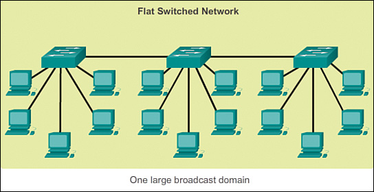
- Early networks were deployed in a flat topology
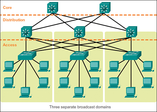
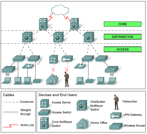
A hierarchical network design involves dividing the network into discrete layers. Each layer, or tier, in the hierarchy provides specific functions that define its role within the overall network. This helps the network designer and architect to optimize and select the right network hardware, software, and features to perform specific roles for that network layer. Hierarchical models apply to both LAN and WAN design.
The benefit of dividing a flat network into smaller, more manageable blocks is that local traffic remains local. Only traffic that is destined for other networks is moved to a higher layer.
A typical enterprise hierarchical LAN campus network design includes the following three layers:
Access layer: Provides workgroup/user access to the network
Distribution layer: Provides policy-based connectivity and controls the boundary between the access and core layers
Core layer: Provides fast transport between distribution switches within the enterprise campus
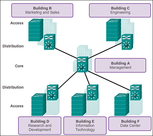
Notice that each building is using the same hierarchical network model that includes the access, distribution, and core layers.
There are no absolute rules for the way a campus network is physically built. While it is true that many campus networks are constructed using three physical tiers of switches, this is not a strict requirement. In a smaller campus, the network might have two tiers of switches in which the core and distribution elements are combined in one physical switch. This is referred to as a collapsed core design.
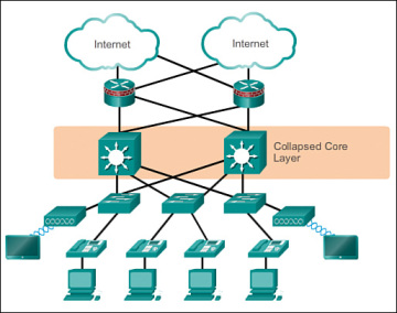
However, many small enterprise networks do not grow significantly larger over time. Therefore, a two-tier hierarchical design where the core and distribution layers are collapsed into one layer is often more practical. A “collapsed core” is when the distribution layer and core layer functions are implemented by a single device. The primary motivation for the collapsed core design is reducing network cost, while maintaining most of the benefits of the three-tier hierarchical model
http://www.ciscopress.com/articles/article.asp?p=2202410&seqNum=4
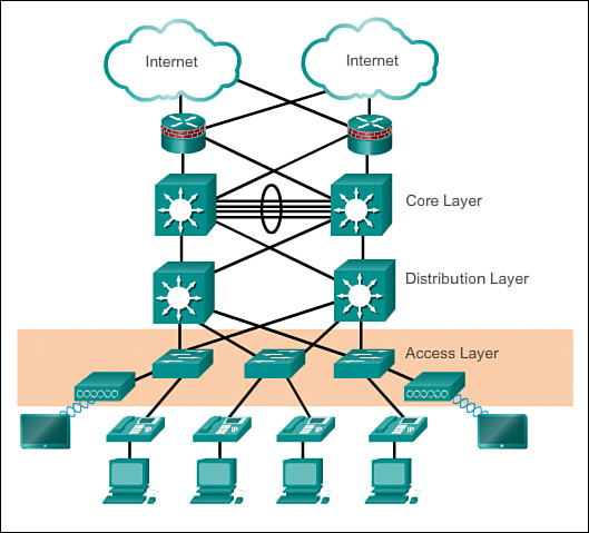
Distribution Layer–aggregates the data received from the access layer switches before it is transmitted to the core layer for routing to its final destination. The distribution layer controls the flow of network traffic using policies and delineates broadcast domains by performing routing functions between virtual LANs (VLANs) defined at the access layer. Devices: high-performance switches to ensure reliability
Core Layer–high-speed backbone of the internetwork Devices: routers, switches capable of forwarding large amounts of data quickly
http://blog.router-switch.com/2014/04/network-design-with-examples-core-and-distribution/
MicroNugget: What is MPLS?
interface independence
Quality of Service,QoS
MicroNugget: What is Multi-Protocol Label Switching (MPLS)?
for packet forwarding decision MPLS uses labels,instead of using IP addresses or layer3 information
label is attached to every single packet
packet forwarding based on label takes less resources compared to IP addresses,
MPLS applications such as layer3 VPNs,Pseudowire
building label based forwarding table
label swapping
MPLS Part 1: The Basics of Label Switching
high-performance forwarding
QoS traffic engineering
e.g:retail sector, Point-Of-Sale(POS) devices sending data to data centers
Applications of MPLS within VPN
Point-to-Point: leased line over VPN, called pseudo-wire
Private LAN Service:interconnecting multiple LANs based in different sites
MPLS does not care what underlying protocol is used (e.g: PPP,DSL,PDH,ATM,SDH/SONET,Ethernet etc)
MPLS maps onto layer2 protocol and provides common fast divison transport method over packet-switched networks(PSN)
MPLS is in OSI between layer2 and layer3, "layer 2.5"
MPLS routers do two tasks
1-map onto any layer2 protocol
2-check IP packet above as it arrives at the transport network and sends it on own its way
difference between routing and switching
which network and which exit port? router asks
packet reference id ,input port id ? switch
MPLS:Switch if possible,Route if necessary
Label switch router(LSR), switch+router
Label Edge Router(LER),known as edge LSR,provider edge router(PER)
MPLS domain,LSR,
packet from IP domain arrives at Ingress LER,
Ingress LER checks layer3 information on the packet
Ingress LER checks its lookup table
Ingress LER finds a reference called forwarding equivalence class(FEC) for the incoming packet
label for FEC added to packet which is a number
packer is forwarded to MPLS domain
label is held in shim header
shim header is between layer3(IP) and layer2
label swapping
packet arrives at egress LER,
egress LER pops/removes the label and forwards the packet to IP domain
label switched path(LSP) is established by label distribution protocol(LDP) or Resource Reservation Protocol-Traffice Engineering (RSVP-TE)
LSPs are one-directional
label operations(push,swap,pop)
FEC does not change, label changes, label swapping
- Pseudowire ( sometimes spelled as "pseudo wire" or abbreviated as PW) is a mechanism for emulating various networking or telecommunications services across packet-switched networks that use Ethernet, IP, or MPLS. Services emulated can include T1 leased line, frame relay, Ethernet, ATM, TDM, or SONET/SDH. As defined in RFC 3985 ("Pseudo Wire Emulation Edge-to-Edge [PWE3] Architecture") a pseudowire delivers the bare minimum of functionality necessary to emulate a wire with some required degree of fidelity for some specific service definition.
Required functions for PWs
Encapsulating service-specific bit streams, cells, or protocol data units (PDUs) that appear at some ingress port, then ferrying them across some IP path or through an MPLS tunnel.
Occasionally managing order and timing of incoming PW traffic so as to properly emulate a service with the necessary fidelity (TDM and ATM are good examples where timing issues are very important).
Seen from the perspective of customer edge equipment (CE), a PW appears to be an unshared link or a circuit for some designated service.
https://searchnetworking.techtarget.com/definition/pseudowire
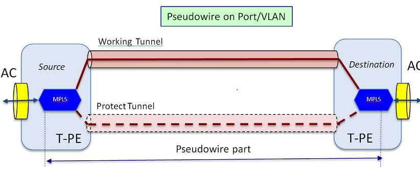
Pseudowires(PW) are used to provide end-to-end services across an MPLS network. They are the basic building blocks that can provide a point-to-point service as well as a multipoint service such as VPLS, which is practically a mesh of PWs used to create the bridge domain across which the packets flow.
https://www.cisco.com/c/en/us/support/docs/multiprotocol-label-switching-mpls/mpls/212007-Pseudowire-Concepts-and-troubleshooting.html
No comments:
Post a Comment